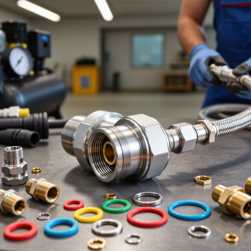
Choosing the right Quick Connect Fitting is not simply a matter of matching pipe size. It requires practical judgment, verified specifications, and an understanding of the working environment. Pressure, temperature, fluid type, vibration, corrosion, and connection frequency all influence the final choice. A fitting that performs well in a clean workshop may fail quickly beside an outdoor compressor.
Paul J. Michael, a respected fluid-power educator and author, once emphasized, “A component is only as reliable as the system around it.” This principle deserves attention. The fitting, hose, seal, coupling body, and installation method must work together. A stainless-steel Quick Connect Fitting may resist moisture, but its seal material could still react badly with certain chemicals. Small details matter.
Start with the operating pressure and temperature range. Then confirm the media compatibility and required flow rate. Examine the connection profile carefully. ISO, NPT, BSP, and metric threads are not interchangeable. Forced assembly is a warning sign. Stop there.
Field experience also reveals less obvious concerns. Dust caps protect exposed couplings. Locking sleeves reduce accidental disconnection. Swivel options can limit hose twisting near moving equipment. Yet product descriptions can be incomplete, and I have seen technically suitable fittings used in unsuitable locations. That mistake is easy to repeat.
Reliable selection involves documentation, testing, and honest review of operating conditions. When uncertainty remains, consult the manufacturer or a qualified fluid-power engineer. The cheapest fitting is not always the economical one. A leak, shutdown, or damaged hose can cost far more than the original purchase.
Before choosing a quick connect fitting, define what it must do in the actual system. Identify the fluid or gas, its temperature, and whether it carries particles or leaves residue. A fitting used with clean water may behave differently with oil or a mildly abrasive mixture. Check the connection size and available space, too. Measure the hose or port rather than relying on a quick visual estimate.
Small mismatch, big trouble.
Next, record normal and peak operating pressure, flow rate, and how often the connection will be attached and removed. Pressure can rise during startup or when a valve closes, so the steady reading may not tell the whole story. Consider vibration, outdoor exposure, and cleaning chemicals near the connection. In a workshop, a fitting may sit beside a warm motor and be handled with oily gloves; those details matter. Specify the required shutoff behavior when disconnected, and verify the fitting’s pressure and temperature ratings against the system conditions. Leave an appropriate safety margin. I have seen selection notes omit brief pressure spikes because they seemed unlikely; that assumption deserves a second look. A short test under controlled operating conditions can reveal leaks, awkward handling, or an unexpectedly restrictive flow path before the fitting is put into regular service.
How to Choose the Right Quick Connect Fitting?
Choosing a quick connect fitting starts with the connection method, not appearance. Push-to-connect fittings suit clean tubing and fast installation. They work well in pneumatic lines, but the tube must be cut squarely. Threaded fittings provide a firm connection for metal ports and higher mechanical loads. Use thread sealant only when the fitting design allows it. Hose barbs need a suitable clamp, especially where vibration or pressure changes occur. Cam-lock couplings connect hoses quickly, making them practical for temporary fluid transfer.
Material compatibility matters. Stainless steel handles corrosion better than ordinary steel. Brass often suits air and water systems. Plastic may reduce weight, but temperature and pressure limits require careful checking. Confirm the working pressure, temperature range, tube size, and fluid type before installation. A fitting may look secure and still leak. I have seen this happen after skipping a simple tube inspection.
Tips: Clean the port before connection. Check the sealing surface for scratches. Push tubing fully into push-fit fittings, then pull gently to verify engagement. For threaded connections, avoid excessive tightening, which can crack softer ports. Test the assembled line at low pressure first. Leave room for disconnection and inspection. My early selections focused too much on speed; service access deserved equal attention.
Choosing a quick connect fitting starts with the fluid, not the fitting itself. Check temperature, pressure, chemical exposure, and outdoor conditions. Stainless steel suits corrosive environments, while brass often works well with clean air and water. Engineering polymers can reduce weight, but some soften under heat. Seal material matters too. A seal that resists oil may fail with solvents. I have seen small compatibility errors become swollen seals and slow leaks.
Measure the tube’s outside diameter with calipers. Do not rely on appearance. A 10 mm tube is not automatically interchangeable with a 3/8-inch tube. Confirm the fitting’s rated pressure after considering temperature and repeated connection cycles. Larger ports may improve flow, but they can add unnecessary bulk. Smaller passages can create pressure loss, especially near valves or long hose runs. Check insertion depth and release-sleeve clearance before installation. Tight spaces are easy to overlook.
Thread standards require particular care. NPT threads are tapered, while BSPP threads are parallel and usually need a separate sealing method. Metric threads also differ from imperial sizes, even when they look close. Never force a mismatched thread. It may assemble briefly. That does not make it safe. Verify the thread form, pitch, gender, and sealing face against technical drawings or certified specifications. A low-pressure leak test is sensible after assembly. My own checks are not perfect, so I remeasure after installation and inspect for movement, abrasion, and seal distortion.
Choosing the right quick connect fitting starts with the working pressure, not the catalog maximum. Check both continuous pressure and short pressure surges. A hydraulic line can spike when a valve closes suddenly. Temperature also changes performance. Heat may soften seals, while cold can reduce flexibility and increase leakage risk. Select a fitting with a verified safety margin at the actual operating temperature.
Flow requirements deserve equal attention. A narrow passage may create pressure loss, even when the connection size looks correct. Compare the fitting’s internal bore, flow coefficient, and hose size with the pump or valve requirements. Measure real flow when possible. Calculations can miss pulsation, trapped air, or sudden restrictions. That mistake is common.
The conveyed media must match every wetted material. Review compatibility with the fluid, concentration, additives, and cleaning chemicals. Water, oil, compressed air, and aggressive process fluids can affect seals differently. Do not judge compatibility by appearance alone. Request technical data and check temperature limits, permeation resistance, and corrosion behavior. Keep the connection clean during installation. A small particle can damage the sealing surface. I have seen fittings pass an initial leak test, then fail after repeated cycling. Testing under realistic pressure, temperature, and connection frequency reveals more than a single bench check. Reconsider the selection if the data is incomplete.
| Application / Media | Typical Operating Pressure | Typical Temperature Range | Flow Considerations | Preferred Fitting and Seal Materials | Compatibility and Selection Guidance | Key Cautions |
|---|---|---|---|---|---|---|
| Compressed Air | 6–10 bar (87–145 psi) for many plant air systems | Approximately −20 to 80°C (−4 to 176°F), depending on seals | Choose a full-flow or high-flow design when pressure drop must remain low. Port sizes of 1/4–1/2 in are common for branch lines and tools. | Nickel-plated brass, stainless steel, engineering polymer; NBR or polyurethane seals | Suitable for general pneumatic tools, automation, and instrumentation when the fitting rating exceeds the system pressure. | Drain condensate and use clean, dry air. Do not use oxygen-service fittings unless specifically cleaned and approved for oxygen. |
| Water and Glycol-Water Mixtures | Commonly 4–16 bar (58–232 psi) in industrial and HVAC circuits | Approximately 0–90°C (32–194°F); freeze protection may extend the lower limit | Use a low-restriction bore for circulation loops. Size the fitting to limit velocity and avoid excessive pressure loss. | Brass, stainless steel, or compatible thermoplastics; EPDM seals are commonly used for hot water and glycol solutions | EPDM generally performs well with water and many glycol mixtures. Confirm concentration and additives before selection. | EPDM is generally unsuitable for petroleum oils and many hydrocarbon fuels. Check corrosion resistance for treated or deionized water. |
| Hydraulic Mineral Oil | 100–350 bar (1,450–5,075 psi) is common; higher-pressure designs are available | Approximately −30 to 100°C (−22 to 212°F), subject to the fitting and seal rating | Use a hydraulic-rated coupling with adequate nominal bore. Account for continuous flow, pressure spikes, and pressure drop across the valve poppet. | Carbon steel or stainless steel; NBR seals are common, with FKM used for higher-temperature service | Select using the maximum working pressure, not average pressure. Confirm impulse, burst, and connection ratings. | Never substitute a low-pressure pneumatic coupling. Pressure must be fully relieved before disconnecting unless the coupling is specifically rated for that function. |
| Water-Glycol Hydraulic Fluid | Often 70–250 bar (1,015–3,625 psi), depending on the system | Approximately −20 to 90°C (−4 to 194°F) | Flow capacity should be checked with the actual fluid viscosity, which can differ significantly from mineral oil. | Stainless steel or compatible plated steel; EPDM seals are commonly considered for water-glycol fluids | Verify seal compatibility with the exact fluid formulation, concentration, and corrosion inhibitors. | Do not assume a seal suitable for mineral oil will work with water-glycol fluid. Check galvanic corrosion when dissimilar metals are joined. |
| Fuel and Petroleum-Based Fluids | Usually 3–20 bar (44–290 psi) in transfer and service applications | Approximately −30 to 80°C (−22 to 176°F), depending on fuel and seal material | Use a bore large enough to prevent excessive restriction and vapor formation. For fuel transfer, consider flow-induced static electricity. | Stainless steel, compatible plated steel, or fuel-rated thermoplastics; NBR or FKM seals are commonly used | Confirm compatibility with gasoline, diesel, biofuel blends, aromatic content, and additives individually. | Use anti-static, bonded, or electrically conductive components where required. Avoid EPDM with petroleum-based fuels. |
| Mild Chemicals and Cleaning Solutions | Often below 10 bar (145 psi), but process systems may be higher | Typically 5–80°C (41–176°F), depending on chemical concentration | Evaluate chemical viscosity and the pressure drop caused by the internal shut-off valves. A larger bore may be needed for viscous liquids. | 316 stainless steel or chemically resistant thermoplastics; EPDM, FKM, or PTFE-based seals depending on the chemical | Compatibility must be checked against concentration, temperature, exposure time, and mechanical stress. | Do not rely only on a general material chart. Oxidizers, solvents, acids, and alkaline cleaners can behave differently at elevated temperatures. |
| Steam and High-Temperature Water | Commonly 3–16 bar (44–232 psi), with pressure-temperature limits carefully linked | Approximately 120–200°C (248–392°F) for many industrial services | Use a steam-rated, high-temperature coupling with minimal dead volume. Calculate condensate behavior and pressure drop. | Stainless steel or high-temperature steel; graphite, PTFE, or specially rated elastomer seals | Use only fittings specifically rated for saturated steam or the intended high-temperature service. | Pressure ratings often decrease as temperature rises. Standard pneumatic or general-purpose hydraulic couplings may fail rapidly in steam. |
| Vacuum Service | From atmospheric pressure down to the specified vacuum level; some designs support approximately −0.9 bar gauge | Typically −20 to 80°C (−4 to 176°F), subject to seal design | Internal leakage and dead volume are more important than nominal flow alone. Select a coupling designed to minimize air ingress. | Stainless steel, brass, or suitable polymer; silicone, FKM, or other vacuum-compatible seals | Confirm vacuum tightness, leak rate, seal permeation, and whether the coupling can be connected under vacuum. | Some quick connects seal well under positive pressure but allow unacceptable leakage under vacuum. |
| Breathing Air or Medical Gas | Application-specific; commonly 4–10 bar (58–145 psi) for distribution systems | Typically 5–50°C (41–122°F) | Prioritize stable flow, low pressure drop, and correct gas-specific connection geometry. | Materials and seals must meet the applicable cleanliness and gas-service requirements | Use only components approved for the specific gas and service classification. | Gas-specific connectors help prevent accidental cross-connection. Oxygen service requires controlled cleaning and compatible materials. |
| High-Purity or Corrosive Gas | Often 1–20 bar (15–290 psi), depending on the process and gas system | Commonly 5–60°C (41–140°F) | Use an internal geometry that minimizes particle generation, dead volume, and adsorption when required. | Electropolished 316L stainless steel; seal selection may include FKM, FFKM, PTFE, or other qualified materials | Specify surface finish, cleaning level, leak rate, and material compatibility with the exact gas. | Reactive, toxic, or oxidizing gases require dedicated engineering review, leak testing, and applicable regulatory controls. |

Selection Guide
Choosing a quick connect fitting starts with evidence, not appearance. In field inspections, I check material certificates, pressure ratings, and production traceability. A polished surface proves little. Inspect threads, seals, locking sleeves, and contact surfaces for scratches or distortion. The fitting must match the fluid, temperature, pressure, and tubing material. Small mismatches can cause leaks, swelling, or sudden disconnection. Ask whether testing covers repeated connection cycles. That question is often overlooked.
Safety depends on correct selection and controlled installation. Relieve system pressure before connecting or removing any fitting. Then confirm the port is clean and properly aligned. Never force a fitting into a mismatched thread. Follow the manufacturer’s torque range, although real installations may require careful judgment. Over-tightening can damage seals, while under-tightening can allow movement. Use protective caps when the connection is exposed to dust or moisture.
After installation, perform a low-pressure leak test before full operation. Watch for bubbles, odor, vibration, or heat around the joint. Record the date, operating conditions, and inspection results. During maintenance, replace hardened seals and inspect locking mechanisms. Do not reuse damaged components. I have seen a fitting pass an initial test and fail later. That experience changed my inspection habits. Inspection intervals should reflect duty cycles, not guesswork. For critical applications, a qualified engineer should verify compatibility.
Copyright © 2025 The Toolroom Inc. All Rights Reserved.
Website Design St Louis by IQComputing