What Is Fast CNC Machining and How Does It Work?
Fast CNC machining describes the rapid production of accurate parts from metal, plastic, or composite materials. It relies on computer-controlled cutting, carefully programmed toolpaths, and stable machine performance. A digital CAD model becomes manufacturing instructions through CAM software. The CNC controller then guides cutting tools across the workpiece. Feed rates, spindle speed, depth of cut, and tool selection all influence the result.
The phrase can mislead. Fast does not always mean better. A rushed operation may leave chatter marks, sharp burrs, overheated edges, or hidden dimensional errors. Very small differences matter. As Dr. Tony Schmitz, a machining dynamics researcher, explains, “High-speed machining is a systems problem, not a single-machine problem.” His point reflects practical shop-floor experience. The machine, tool, material, fixture, coolant, and operator must work together.
This article examines what fast CNC machining really means and how the process works. It follows the journey from digital design to finished component. Readers will see how high spindle speeds remove material efficiently, while sensors and inspection equipment protect accuracy. A titanium bracket may emerge quickly, but its quality depends on more than cutting speed. Tool wear can change halfway through a batch. Heat can shift dimensions. Programming mistakes can repeat perfectly.
That is the uncomfortable part. Faster production can expose weak planning. Reliable results require testing, measurement, and occasional restraint. The best process is not always the fastest one. It is the one that delivers consistent parts, practical costs, and dependable performance.
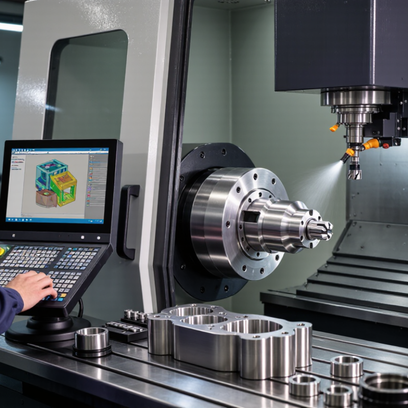
What Is Fast CNC Machining?
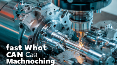
Fast CNC machining is the controlled removal of material at the shortest practical production time. A computer converts a CAD model into toolpaths, then the machine moves cutting tools along programmed axes. Speed depends on spindle rotation, feed rate, cutting depth, tool geometry, material, and setup efficiency.
It is not simply running the spindle faster. Speed is relative. In practical shop work, an aluminum housing may use aggressive feeds and shallow finishing passes, while stainless steel needs slower cutting to control heat and tool wear.
Operators also reduce idle time through automatic tool changes, optimized paths, and stable fixturing. A 2023 global smart-manufacturing survey of 816 manufacturing executives reported that 86% expected smart-factory investment to improve competitiveness within five years. That finding supports faster digital workflows, but it does not guarantee faster cutting.
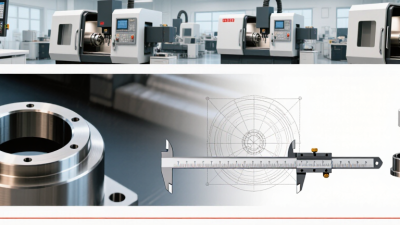
Quality still controls the definition. ISO 230-2 specifies methods for evaluating positioning accuracy and repeatability in machine tools. These checks matter when a rushed process produces holes that shift by fractions of a millimeter. Inspection may use probes, gauges, or coordinate-measuring equipment after machining.
The trade-off is real. A shorter cycle can increase burrs, vibration, scrap, or tool replacement costs. Experienced machinists therefore compare total cycle time, not only cutting time. The 2024 U.S. manufacturing labor outlook also shows continued pressure to produce more with fewer skilled workers, making repeatable automation increasingly valuable. Yet every material and geometry still needs testing. That part is easy to underestimate.
Which Steps Make CNC Machining Faster?
What Is Fast CNC Machining and How Does It Work?
Fast CNC machining depends less on simply increasing spindle speed. It depends on removing delays between operations. According to the 2024 World Robotics report, manufacturers installed 541,302 industrial robots worldwide in 2023, a 10% annual increase. That growth reflects a wider shift toward automated material handling, loading, and inspection.
Which Steps Make CNC Machining Faster?
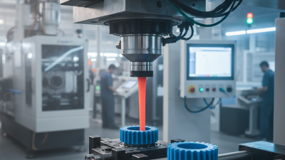
The process starts with a production-ready CAD model. Clear tolerances prevent repeated questions and costly revisions. Engineers then select the fewest setups possible. A rigid fixture can hold several parts at once, while standardized tools reduce tool-changing time. High-speed toolpaths also matter. Adaptive cutting keeps chip load steadier and avoids sudden cutter engagement. It can shorten cycle time, but only when feeds, speeds, and material data are verified.
Simulation catches collisions before metal reaches the spindle. That saves more time than rushing the first cut. In a 2023 manufacturing survey from the National Institute of Standards and Technology, small and medium manufacturers commonly identified setup, scheduling, and process integration as major productivity barriers. The lesson is practical: faster machining often begins outside the machine.
In-process probing can measure features without removing the part. Automated inspection reduces handling and helps detect drift early. Still, faster is not always better. Excessive speed may create heat, chatter, or premature tool wear. I have seen cycle-time targets fail because finishing passes were planned too aggressively. A balanced process usually wins: stable fixturing, verified toolpaths, short setups, and inspection placed at the right moment.
What Materials and Machines Are Used?
Fast CNC machining depends on matching the material with the right machine, cutter, and production strategy. Aluminum is widely selected for prototypes because it cuts quickly and removes heat efficiently. Steel offers greater strength, but it needs slower cutting speeds and stronger tooling. Titanium is lighter than steel, yet its low thermal conductivity makes machining demanding. Engineering plastics can reduce weight, although heat may distort thin walls.
The machine matters just as much. Three-axis mills suit flat pockets and simple prismatic parts. Five-axis machines reach angled surfaces with fewer setups, reducing alignment errors. Turning centers produce shafts, pins, and rotational components. According to Grand View Research’s 2024 CNC machine market analysis, automation and multi-axis equipment are major growth drivers in modern manufacturing. That trend reflects shorter setup times, not just faster spindle speeds.
Tool selection also affects quality. Carbide cutters commonly handle aluminum, steel, and titanium, while coated tools can improve wear resistance. Coolant controls heat and carries chips away from the cutting zone. The U.S. Department of Energy identifies machining as a significant energy user in industrial production, so aggressive cutting is not automatically efficient. Faster is sometimes wasteful. A thin aluminum wall may vibrate, and a hard titanium pocket may need several gentle passes. Material choice is not always elegant. Practical teams check hardness, thermal behavior, chip formation, and batch size before promising a delivery date.
How to Evaluate Fast CNC Machining Results
Fast CNC machining uses computer-controlled cutting to produce parts quickly from digital designs. Evaluating the result requires more than checking whether the part looks complete. Speed only matters when accuracy, consistency, and function remain acceptable. A part can leave the machine quickly and still fail during assembly. Inspect it carefully.
Begin with the drawing and its critical dimensions. Measure holes, wall thicknesses, lengths, and datums with calibrated tools. Use a coordinate measuring machine for complex profiles or tight tolerances. Compare actual readings with the specified limits, not with visual expectations. Record the temperature, material, and inspection equipment. These details can explain unexpected variation.
Surface quality also matters. Look for burrs, tool marks, chatter, discoloration, and sharp edges. A smooth-looking surface may still exceed the required roughness value. Test it when the application depends on sliding, sealing, or fatigue resistance. Check hole alignment with mating components, rather than measuring holes in isolation. Fit is evidence.
A reliable evaluation includes repeatability. Inspect several parts from the same run and compare their measurements. One perfect sample proves very little. If dimensions drift, review tool wear, workholding, cutting parameters, and machine temperature. In practice, rushed inspections often miss small burrs that prevent proper assembly. That mistake is easy to underestimate. A useful report should include measured values, photographs, deviations, and corrective actions. It should also admit uncertainty when a feature was difficult to measure. Perfect confidence is not always professional.
How to Evaluate Fast CNC Machining Results
The chart shows representative dimensional deviations measured after fast CNC machining of an aluminum prototype. Lower values indicate better dimensional accuracy. A deviation within ±0.05 mm is commonly accepted for general CNC work, although the required tolerance depends on the drawing, material, machine, tooling, and inspection method.