
Choosing the right Solenoid Valve is not a matter of selecting the lowest price or the largest connection size. It is a practical engineering decision that affects flow control, equipment safety, maintenance time, and operating costs. A valve that works well on a test bench may fail in a dusty factory, a cold outdoor cabinet, or a system with pressure fluctuations.
Valve specialist Les Skinner offers a useful reminder: “The best valve is the one that matches the application.” That principle sounds simple, but many purchasing decisions ignore it. Before choosing, identify the fluid, pressure range, temperature, flow rate, response time, port size, voltage, and duty cycle. Water, compressed air, steam, oil, and aggressive chemicals require different body and seal materials. A normally closed Solenoid Valve may suit a safety shutoff system, while a normally open design may be safer during power loss.
Installation details also matter. Check the arrow on the body. Confirm the coil voltage. Protect the valve from excessive vibration and contaminated media. A filter placed upstream can prevent small particles from blocking the orifice. These details seem minor.
They are not.
Experience also teaches humility. Catalog data rarely describes every real-world condition. A valve may become noisy, slow, or unexpectedly hot after installation. Therefore, compare manufacturer specifications, request technical confirmation, and test the selected model under realistic pressure and temperature conditions. The right choice is not merely the valve that fits the pipe. It is the valve that performs reliably within the entire system.
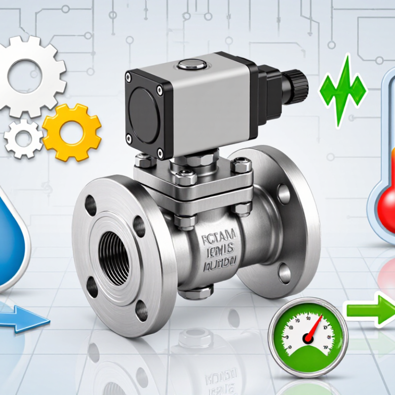
Define media, pressure, temperature, and flow before comparing valve sizes. These four inputs control reliability more than the port diameter alone. Identify the medium precisely: water, air, oil, steam, or a corrosive chemical. Check its viscosity, cleanliness, and compatibility with internal seals. Small particles can block a narrow orifice. A clean-looking fluid may still cause trouble.
Record the minimum and maximum pressure, not only the normal operating value. Many valves require a pressure difference to open correctly. Others operate with zero differential pressure. Confirm both conditions in the technical data.
Temperature also needs attention. Measure the actual media temperature and the surrounding temperature near the coil. Heat can shorten coil life and change seal performance. Flow should be expressed clearly, such as liters per minute or standard cubic meters per hour. I have seen sizing errors caused by mixing these units. It is an easy mistake.
Tips: Keep a simple sizing sheet. Write down media, pressure range, temperature range, required flow, connection size, and cycle frequency. Then compare the valve’s Cv or Kv value under real conditions. Do not select a valve only because its body matches the pipe. A larger valve may respond poorly at low flow. A smaller valve may create excessive pressure loss. When uncertain, test one unit with the real medium and operating cycle. Catalog values are useful, but field conditions can be less tidy.
Choosing valve function starts with the equipment’s actual movement, not the catalog photograph. A 2/2 valve has two ports and one flow path. It suits simple isolation, filling, draining, or dispensing. A 3/2 valve has three ports and two switching positions. It can supply and exhaust a single-acting actuator, such as a spring-return cylinder. I once saw a 3/2 valve selected for a basic water line because it looked more versatile. It added cost and connection errors without improving control.
Then decide whether the valve should be normally closed or normally open. Normally closed blocks flow when the coil is de-energized. It may suit systems that should stop flow during power loss. Normally open allows flow without electrical power. It can suit cooling or ventilation circuits that should continue during a control failure. Do not choose by habit. Ask what the machine must do when nobody is watching. That question is easy to miss.
Check the medium, pressure, temperature, port size, and flow rate against the datasheet. A valve may fit the pipe yet fail because its minimum pressure differential is too high. Confirm flow direction and coil voltage before installation. Test the fail position with power removed. Record the result. Field experience also teaches caution: a clean schematic can hide slow exhaust, trapped pressure, or a weak spring. When the application remains uncertain, have a qualified engineer review the circuit and operating conditions.
| Valve Function | Port / Position Meaning | De-energized State | Energized State | Typical Applications | Main Selection Considerations |
|---|---|---|---|---|---|
| 2/2 Normally Closed (NC) | Two ports and two positions: inlet and outlet. | Inlet and outlet are closed; flow is shut off. | Inlet and outlet are connected; flow passes through the valve. | Water, air, gas, fuel, lubrication, cooling, dispensing, and safety shutoff circuits. | Choose this function when the valve should stop flow automatically if electrical power is lost. |
| 2/2 Normally Open (NO) | Two ports and two positions: inlet and outlet. | Inlet and outlet are connected; flow passes through the valve. | Inlet and outlet are closed; flow is shut off. | Continuous cooling, ventilation, purge, bypass, and systems that must flow during a power failure. | Choose this function when continued flow is preferred or required during loss of electrical power. |
| 3/2 Normally Closed (NC) | Three ports and two positions, commonly supply (P), outlet/actuator (A), and exhaust (R). | P is blocked; A is connected to R, so the actuator/output side is exhausted. | P is connected to A; R is blocked, so the actuator/output side is supplied. | Single-acting pneumatic cylinders, spring-return actuators, clamps, grippers, and pilot control circuits. | Use when the output must be vented and the actuator must return to its spring position when power is removed. |
| 3/2 Normally Open (NO) | Three ports and two positions, commonly supply (P), outlet/actuator (A), and exhaust (R). | P is connected to A; R is blocked, so the output side is supplied. | P is blocked; A is connected to R, so the output side is exhausted. | Single-acting actuators that should remain pressurized or active when electrical power is unavailable. | Use when the actuator should be supplied in the normal, de-energized condition and vented after energizing. |
Choosing the right solenoid valve begins with the fluid, not the pipe size. Identify the chemical, concentration, temperature, pressure, and exposure time. A solvent that seems mild at room temperature may attack a seal when heated. Body materials also matter. Stainless steel often handles demanding fluids, while engineered plastics can suit lighter chemical service. Verify the actual fluid data.
Seals deserve equal attention. EPDM performs well with many water-based fluids but may swell in oils. FKM handles many oils and elevated temperatures, yet it is not suitable for every aggressive chemical. PTFE offers broad chemical resistance, but its mechanical behavior and sealing design require careful review. Small incompatibilities can cause leakage, sticking, or sudden valve failure.
Do not rely on a general compatibility chart alone. Compare the chart with the valve supplier’s tested limits and your operating conditions. Check temperature peaks, pressure changes, cleaning chemicals, and idle periods. In practical maintenance, failures often follow an overlooked detail, such as concentrated fluid trapped inside the valve. That shortcut deserves doubt. If the application is unusual, request immersion data or a written engineering recommendation. Material selection is never perfectly universal. A careful review may reveal that the cheapest compatible option is not the safest long-term choice.
The chart shows representative upper continuous service temperatures for commonly used valve body and seal materials. Actual limits depend on pressure, concentration, exposure time, mechanical design, and the specific compound or grade. Brass and stainless steel are commonly selected for general liquid and gas service, while PVC is limited to lower temperatures. NBR is often suitable for mineral oils, EPDM is generally preferred for hot water and many dilute chemicals, FKM performs well with oils and elevated temperatures, and PTFE offers broad chemical resistance across a wide temperature range. Always verify both body and seal compatibility with the process medium.
Choosing a solenoid valve starts with three numbers: Cv, response time, and duty cycle. According to IEC 60534-2-1, Cv estimates water flow through a valve at a defined pressure drop. For water, a Cv of 1 delivers roughly 1 US gallon per minute at 1 psi differential pressure. The figure changes with gas compressibility, temperature, and fluid density.
Response time needs careful testing. A 5 ms valve may suit fast air pulses, but the real result depends on wiring, pressure, seal friction, and controller output. A 100 ms response can be acceptable for dosing or isolation. It may fail in high-speed sorting. Request test conditions, not just a headline number. Check whether the supplier measures energizing-to-opening or command-to-stable-flow time.
A 100% duty-cycle rating means the coil can remain energized continuously under specified conditions. It does not guarantee a cool enclosure. Coil temperature rises with ambient heat, voltage variation, and restricted airflow. IEC 60079-0 offers useful temperature-class thinking for equipment in controlled industrial environments, while ISO 4414 emphasizes safe pneumatic design and stored-energy control. In practice, I compare the datasheet with logged cycle data from the actual machine. This step is often skipped. It should not be. A larger Cv can increase shock and waste, while an ultra-fast valve can create pressure spikes. The best choice is usually the smallest Cv meeting peak flow, with verified response and continuous-duty thermal data.
Start with the coil voltage, not the valve body. Check whether the control circuit supplies AC or DC, then match the rated voltage exactly. A 24 VDC coil can fail when connected to 24 VAC. Confirm voltage tolerance, power consumption, and connector wiring from the datasheet. In field inspections, loose terminals often cause faults that look like valve failure. Measure the voltage under load. A label alone is not enough.
For outdoor panels, IP65 protection offers dust resistance and protection against water jets. It does not permit immersion or constant flooding. Check the enclosure, cable gland, and connector together, because one weak point can reduce protection.
Pressure class also needs careful review. Compare inlet pressure, outlet pressure, differential pressure, and the valve’s minimum operating pressure. Select seals for the actual medium, temperature, and flow rate. Water service is not automatically suitable for oil, steam, or chemicals.
Applicable standards should match the installation location and system risk. Review electrical safety, pressure equipment, material, and environmental requirements before purchase. Request test reports or declarations from a qualified supplier, not only marketing claims. I once treated a familiar pressure rating as sufficient, then found the minimum differential pressure was unsuitable. That mistake was avoidable. Keep the operating limits visible for maintenance staff, and record the inspection date. Real reliability comes from verifying every detail against the application.
Copyright © 2025 The Toolroom Inc. All Rights Reserved.
Website Design St Louis by IQComputing