
A Power Phase Converter helps single-phase electrical service run three-phase machinery. It is common in workshops, farms, and small manufacturing facilities. Picture a metal lathe starting in a quiet garage. Its motor needs balanced, rotating power. The converter creates that missing phase.
The U.S. Department of Energy reports that motor-driven equipment represents more than half of industrial electricity use. The International Energy Agency also estimates that electric motors consume roughly 70% of industrial electricity worldwide. These figures explain the converter’s value. Better phase conversion can support motor performance, reduce unnecessary equipment replacement, and improve operational flexibility. It does not magically fix every electrical problem.
Mike Holcomb, founder of American Rotary, describes the practical purpose clearly: “A phase converter gives three-phase equipment the power it needs from single-phase service.” That statement is useful, but incomplete. Converter type, motor size, starting load, voltage, and phase balance still matter. The U.S. DOE’s Motor Systems guidance stresses that correct sizing and system-level evaluation influence efficiency more than equipment labels alone.
This guide explains how a Power Phase Converter works, from phase generation to motor startup and load balancing. It compares rotary and static designs. It also examines installation details, including capacitors, idler motors, grounding, and control panels. Some explanations may feel less tidy than expected. Real installations vary. That is the point. A converter that performs well beside one milling machine may struggle with a compressor or hydraulic pump. Careful measurement remains essential.
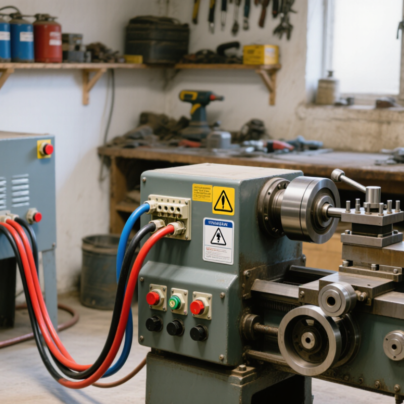
A power phase converter is an electrical device that changes available power from one phase configuration to another. Most commonly, it supplies three-phase power from a single-phase source. This allows three-phase motors and machines to operate where utility service is limited. Its purpose is practical: extend equipment options without replacing every machine or rebuilding the entire electrical supply.
The converter creates additional phase relationships through electronic controls, capacitors, or a rotating motor, depending on its design. A qualified technician should measure voltage, motor horsepower, starting current, and expected operating load before selecting one. These details matter. A machine may start successfully but still receive uneven power during heavy work. That imbalance can increase motor heat, vibration, and maintenance problems. I have seen sizing treated as a simple horsepower calculation, but that approach is incomplete. The converter must also match the equipment’s starting demands and control system. Static units may suit lighter applications, while rotary or electronic systems can provide more consistent operation. The right choice depends on the machine, not just the outlet. Always check wiring, grounding, ventilation, and local electrical requirements with a licensed professional. Clearance and testing are easy to overlook. A reliable installation should be measured under real load, not judged only by whether the motor turns.
| Data Dimension | Key Information | How It Works or Why It Matters | Typical Practical Consideration |
|---|---|---|---|
| Definition | A power phase converter is an electrical device or system that changes the available phase configuration of AC power to supply equipment designed for a different phase arrangement. | It enables selected electrical loads to operate when the available utility service does not match the phase requirements of the equipment. | The converter does not automatically change every electrical characteristic; voltage, frequency, current capacity, and phase balance must also be suitable. |
| Main Purpose | To provide usable three-phase power from a single-phase electrical service or to adapt one phase configuration to another. | This can support three-phase motors and machinery in locations where utility-supplied three-phase service is unavailable or costly to install. | The incoming service must have enough capacity for the converter and the connected load. |
| Single-Phase Power | Single-phase AC power uses one alternating voltage waveform and is common in many residential, small commercial, and light-industrial installations. | It can supply lighting, electronics, heating elements, and many single-phase motors, but it does not create the naturally rotating magnetic field provided by a balanced three-phase supply. | Service ratings are commonly expressed in volts and amperes; available capacity depends on the circuit and utility connection. |
| Three-Phase Power | Three-phase AC power uses three voltage waveforms separated by 120 electrical degrees. | The phase relationship produces a rotating magnetic field that allows three-phase motors to start and run smoothly with high power density. | Equipment nameplates should be checked for rated voltage, frequency, phase, full-load current, and starting requirements. |
| Rotary Phase Converter | A rotary converter uses a three-phase idler motor, capacitors, controls, and protective components to generate an additional phase. | When energized, the idler motor creates a rotating magnetic field. The generated phase combines with the utility phases to supply three-phase output power. | It can operate multiple motor loads, but output voltage balance and motor-starting performance require correct sizing and adjustment. |
| Static Phase Converter | A static converter uses capacitors and switching components to help a three-phase motor start from a single-phase supply. | After starting, the motor generally operates as a single-phase-fed motor rather than receiving fully generated three-phase power on all terminals. | It is usually intended for selected motor applications and may reduce available motor horsepower or operating efficiency. |
| Digital Phase Converter | A digital converter uses electronic power-switching circuits and control software to synthesize a three-phase output waveform. | Power electronics regulate the output and can provide more consistent phase generation than a basic capacitor-only arrangement. | Electronic units may require attention to heat dissipation, electromagnetic compatibility, programming, and fault protection. |
| Variable-Frequency Drive | A variable-frequency drive, or VFD, converts AC to DC and then reconstructs AC with controlled voltage and frequency. | It can operate a compatible three-phase motor from a single-phase input in appropriately sized applications while also controlling motor speed. | The VFD, motor, wiring, and protective devices must be selected as a coordinated system; input derating may be required for single-phase supply. |
| Input and Output | The input may be single-phase or another phase configuration, while the output is commonly intended for three-phase motor or machinery loads. | The converter changes the electrical supply arrangement, but the output remains limited by the converter's current and power rating. | Voltage and frequency must match the equipment nameplate. A phase converter is not automatically a voltage transformer or frequency converter. |
| Motor Starting | Motor starting current can be several times higher than normal running current, depending on motor design and load. | The converter must provide sufficient short-term capacity to accelerate the motor without excessive voltage drop or nuisance tripping. | Large motors, high-inertia loads, compressors, and heavily loaded machines generally require careful starting analysis. |
| Load Compatibility | Induction motors are common applications, while sensitive electronic equipment, heating systems, and non-motor loads may have different requirements. | Some equipment needs balanced three-phase power, a neutral conductor, a clean waveform, or tightly regulated voltage. | Review the equipment manual and electrical drawings before connecting non-motor loads to a converter output. |
| Sizing Factors | Important sizing inputs include motor horsepower or kilowatts, voltage, full-load current, number of motors, starting method, duty cycle, and simultaneous loading. | Correct sizing helps prevent overheating, low-voltage conditions, poor motor torque, and repeated protective-device operation. | The largest motor may determine the starting requirement, while the total running load determines continuous capacity. |
| Efficiency and Power Quality | Conversion introduces losses, and some designs can produce voltage imbalance, waveform distortion, or electrical noise. | Efficiency and output quality affect motor temperature, energy use, operating life, and the performance of sensitive equipment. | Measure phase-to-phase voltages under representative load conditions and follow the converter manufacturer's specified limits. |
| Protection Requirements | Typical installations require overcurrent protection, disconnecting means, grounding, suitable conductors, and motor overload protection. | These measures help protect people, wiring, motors, and the converter from short circuits, overloads, and abnormal operating conditions. | Installation should follow applicable electrical codes and be performed or inspected by a qualified electrical professional. |
| Advantages | Phase converters can avoid the cost or delay of obtaining new utility service and can make existing three-phase machinery usable at a suitable site. | They can provide a practical solution for workshops, agricultural facilities, maintenance areas, and small industrial installations. | The total installed cost should include the converter, wiring, protection, controls, commissioning, and maintenance. |
| Limitations | A converter cannot create unlimited electrical capacity and may not provide the same performance as a utility-supplied, balanced three-phase service. | Improper selection can result in unbalanced voltage, reduced motor output, overheating, starting problems, or damage to connected equipment. | Use a utility three-phase connection or a purpose-built power system when the load is large, highly sensitive, or requires strict phase balance. |